Alaskan King Bed Frames: Size, Support and Delivery
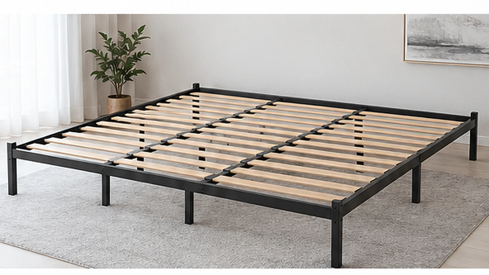
An Alaskan King bed frame must do more than accommodate a large mattress. For the commonly referenced 108 × 108-inch mattress size, the frame needs a compatible support surface, a structure that carries loads through its rails and supports, and a delivery format that reaches the assembly location. Mattress dimensions alone establish none of those conditions. For furniture manufacturers and bed brands, the practical starting point is the mattress specification and finished-bed design—not an enlarged drawing of a conventional king frame. Resolve fit, support and handling together before approving a sample, because changing one can alter the other two.
Confirm the Actual Mattress, Not Just the Size Name
AlaskanKingBeds lists its Original mattress at 108 × 108 inches, while other products in its named range have different dimensions. That makes 108 × 108 inches a useful reference for this discussion, not a universal specification for everything sold under a similar name. The corresponding metric conversion is 2,743.2 × 2,743.2 mm; it is not a manufacturing tolerance or an instruction to make the support frame exactly that size.
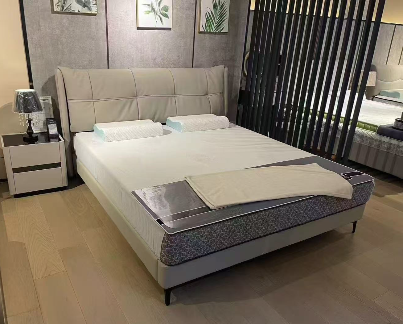
A bed frame for a 108 x 108 mattress may be an exposed platform, an internal support structure inside upholstered rails, or a frame carrying a separate mattress foundation. Those arrangements have different interfaces. In a recessed design, the mattress opening determines whether the mattress fits between the finished rails. In an exposed platform, the supported area and intended edge relationship matter instead. Copying the mattress dimensions into an “overall frame size” field leaves that distinction unresolved.
Separate the Mattress Opening, Support Area and Finished-Bed Footprint
| Dimension | What it controls | What belongs on the drawing |
|---|---|---|
| Mattress dimensions | The item being accommodated | Model, length, width, thickness and its stated dimensional tolerances |
| Mattress opening | Fit between finished surrounding surfaces, when a recess exists | Clear opening, corner details and mattress recess depth |
| Effective support area | Where the mattress or foundation receives support | Slat or deck layout, perimeter support and any interruptions |
| Support-frame dimensions | How the internal structure fits and attaches to the bed body | Frame outline, bracket locations and mounting interfaces |
| Finished-bed footprint | Space occupied by the complete furniture assembly | Outermost bed rails, headboard, footboard and projecting components |
Dimensions also need a defined measurement condition. A bare wooden rail and the same rail after upholstery do not necessarily leave the same clear opening. Specifying only the nominal opening can therefore hide a fit problem that appears during final assembly. Use the finished surfaces as the reference where those surfaces contact or surround the mattress.
Height needs the same treatment: the top of the metal rail, the mattress-bearing surface and the top of the finished mattress are different levels. Adding a separate foundation changes the stack height even when length and width remain unchanged. A section view makes that relationship visible before the headboard, upholstery and support frame are approved independently.
Shilong’s metal and steel-wood bed frame range includes support structures for furniture integration. Distinguishing an internal support frame from a complete finished bed keeps the purchased scope clear; a support-frame quotation should not be read as including a mattress, upholstered surround or headboard.
Match Bed Frame Slats to the Mattress Support Requirements
Can the Frame Be Used Without a Box Spring?
A bed frame without a box spring is appropriate only when the mattress is intended for the support surface provided. Direct-on-slat construction and a frame carrying a separate foundation are not interchangeable specifications. In the first arrangement, the mattress bears on the slats or deck. In the second, the foundation sits between the mattress and frame, and its own bearing requirements become part of the design.
For example, Big Mattress Co.’s published warranty describes a firm, solid-surface, non-spring foundation or suitable adjustable base for its mattresses, together with structural support for the mattress and users. Its requirements illustrate why the mattress supplier’s instructions belong in the frame specification; they are not a universal rule for every oversized mattress.
If the selected mattress requires a support surface that the proposed slatted frame does not provide, resolve that mismatch before sampling. The answer may involve a different support system or a separately specified foundation, rather than simply adding more slats. Any added layer must be included in the height, weight, attachment and packaging review. It is not automatically supplied with the frame.
Slat Gaps and Unsupported Spans Answer Different Questions
The clear gap between adjacent bed frame slats describes the interruptions in the mattress-bearing surface. The unsupported span describes the distance a slat or beam bridges between its supports. A small gap does not, by itself, mean the member underneath is adequately supported.
Consider two proposed layouts with identical slat spacing. One carries each slat between distant outer rails; the other introduces an intermediate supporting rail. Their surface gaps may look the same, but their load paths differ. In beam analysis, deflection depends on span, flexural rigidity, loading and support conditions. Shorter spans can reduce bending deflection under otherwise comparable conditions; the intermediate rail must still carry the load delivered to it.
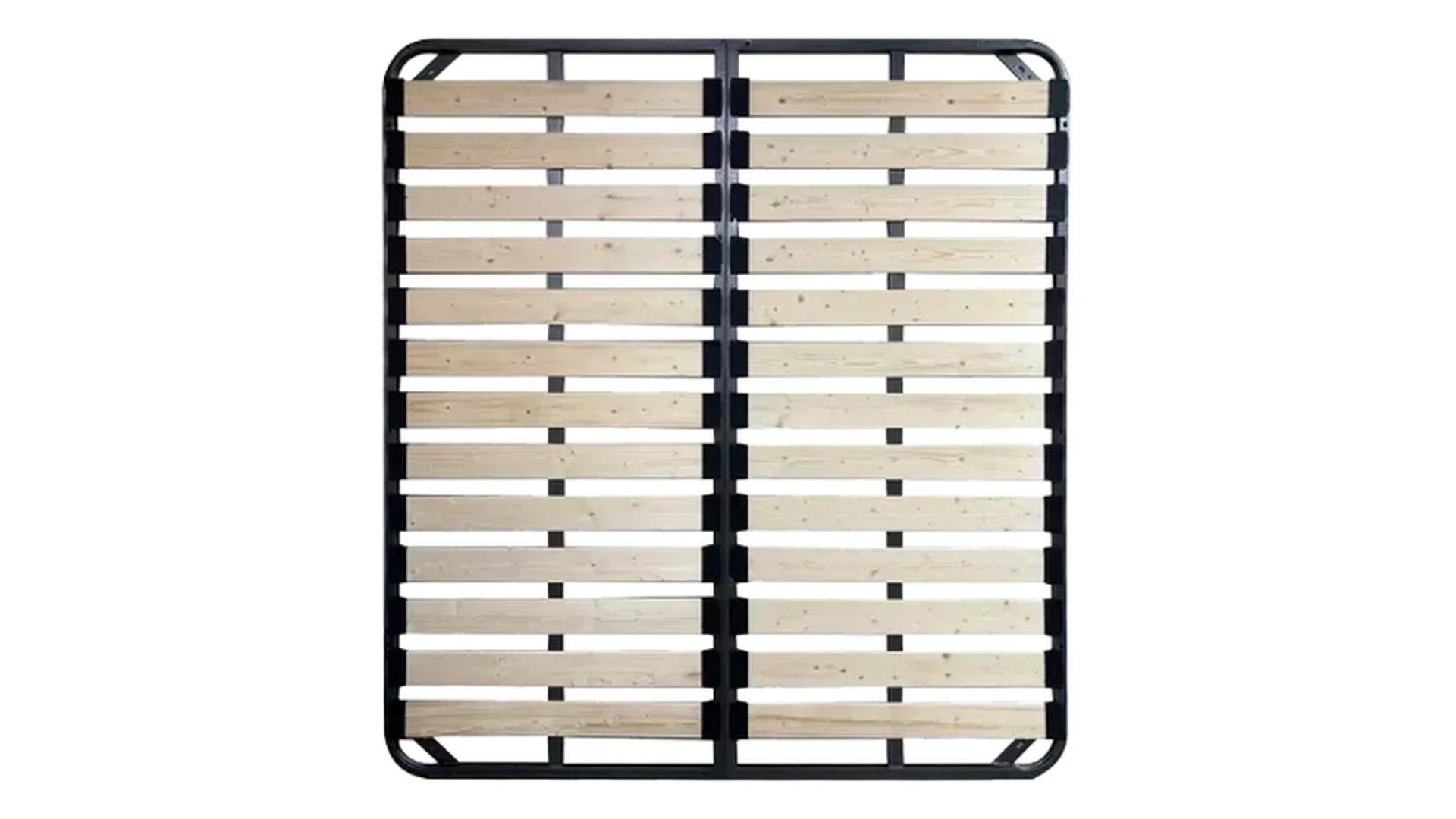
The useful comparison therefore combines slat width, thickness, material and orientation with the locations supporting each member. Look at the complete layout, including the joint between modules: the regular spacing within each panel can conceal a larger interruption where panels meet. A mattress-support requirement applies to the assembled surface, not just to an isolated slat panel.
Review Oversized Bed Frame Support as a Complete Load Path
Compare Support Layouts, Not Just Row Counts
Enlarging the perimeter does not show how the middle of an oversized bed will be supported. Trace the proposed vertical load path from the mattress or foundation, through the slats and rails, through the connections, and finally to the supporting bed body or floor. Each transition needs a physical bearing or connection detail; a line on a plan is not enough.
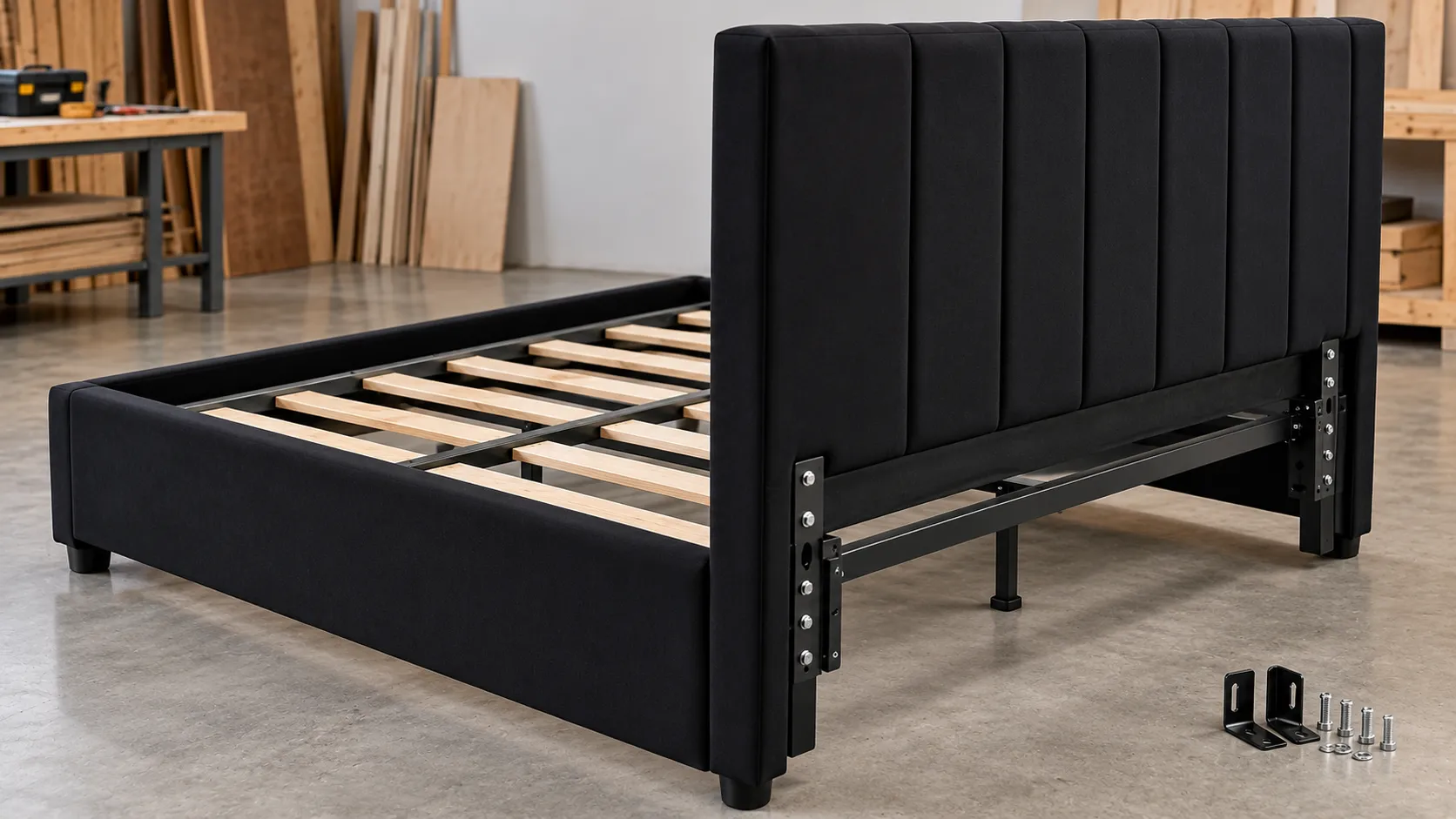
A plan and underside view are particularly useful together. The plan shows the support surface; the underside view reveals where rails, brackets and feet actually meet. A center rail that stops at a folding joint, for example, needs a defined connection or local support arrangement at that location. Otherwise, the drawing does not establish how the two sections act together in use.
The double-row folding support frame and four-row folding support frame provide examples of metal-and-wood structural layouts. Their product descriptions identify customization options, but neither a row count nor a general customization statement establishes the capacity of a specific 108 × 108-inch configuration. Four rows do not automatically mean twice the capacity of two rows.
Bed Frame Support Legs Must Match the Structure Above Them
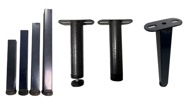
Counting legs is less useful than locating them against the rail layout. A support positioned beneath a loaded rail junction has a different structural role from a foot elsewhere on the perimeter. The assembly drawing should show which members each leg supports and whether the frame also relies on brackets attached to the surrounding furniture.
Floor contact is part of that arrangement. A leg that remains above the floor cannot provide the intended bearing at that point until contact occurs. An uneven support condition can therefore differ from the arrangement assumed in a drawing or test. Where adjustment is part of the proposed design, the instructions need to explain how the frame is set up without lifting other required supports out of contact.
Vertical support also does not settle sideways movement. Corner joints, module connections and the relationship with the outer bed body affect how the assembled frame resists movement. Adding feet is not a substitute for resolving loose joints or an undefined attachment to the furniture. These are separate review questions, especially when a support frame is tested on its own but sold for installation inside another structure.
Plan Delivery and Room Access Before Freezing the Design
A Folding Bed Frame Does Not Necessarily Shorten Every Dimension
Folding and knock-down construction solve different handling problems. A folding bed frame keeps selected sections connected while changing their relative positions. A knock-down, or KD, frame separates into components or modules that are joined during assembly. The relevant comparison is the resulting package and assembly process, not the label alone.
A simple geometric example shows the limitation. Dividing an idealized 108 × 108-inch square support area along one centerline produces two 54 × 108-inch sections. Folding one over the other reduces one plan dimension, but the other remains 108 inches. This is an illustration only—not a Shilong product or carton specification—and it excludes hinges, member thickness, projections and protective packaging.
A KD layout can reduce the longest transported part only if its joints actually divide the members that create the length restriction. Removing short crossmembers while retaining full-length side rails does not solve a longest-part problem. More divisions may improve access, but they also create more connections to assemble and inspect.
| Decision | Folding layout | Knock-down layout |
|---|---|---|
| What limits handling? | Folded length, width, thickness and weight of the connected assembly | Longest indivisible member, largest module and actual packed arrangement |
| What happens at installation? | Unfolding, positioning and securing the intended working configuration | Identifying parts, aligning joints and completing the prescribed assembly sequence |
| What needs structural review? | Continuity and support around folding joints | Load transfer and stability at separable connections |
| What supports the decision? | A folded-envelope drawing, packed sample and unfolding sequence | A parts drawing, packing layout and assembly trial |
Neither format is automatically the cheaper shipment. Compare quotations using the same delivery scope and the actual packed dimensions, weights and handling requirements. A reduction in one dimension is not proof of lower total freight cost, and a compact pack is not automatically faster to assemble.
Check the Largest Package, Longest Part and Assembly Space
Access has three different constraints: the largest package entering the building, the longest rigid part moving through it, and the space required to assemble or unfold the frame. Passing a doorway does not establish that the same item can turn on a landing, enter an elevator or be positioned inside the room.
Use the intended handling condition consistently. If delivery requires unpacking before a stair turn, the route assessment must use the exposed component dimensions, and the handling plan must account for those components outside their protective packaging. A carton-only check cannot demonstrate that process.
The final room layout also needs room for the operation itself. A bed may fit in its finished position while leaving no practical access to a joint against the wall. Assembly instructions and room access should be reviewed together: identify when the frame is turned, unfolded, connected to the bed body or fitted with the mattress foundation. If a step cannot be performed in the available space, revise the sequence or structure before the design is released.
Validate the Complete Assembly Before Bulk Production
A load-capacity figure is meaningful only when its basis is clear. It may refer to occupants, to the mattress and occupants together, or to a particular test arrangement. Even an accurately stated total does not describe where the load was applied, what supported the frame or how movement and damage were assessed. Those details determine whether a result is relevant to the proposed bed.
Separate three questions in the sample review: can the structure meet the agreed strength requirements; is its deformation acceptable in use; and do the assembled joints and supports remain stable under the specified assessment? A demonstration with weight spread across the surface does not answer every question about localized or horizontal loading. SATRA’s technical overview of EN 1725:2023 distinguishes static, impact and stability assessments and identifies assembly and use information as part of the standard’s requirements.
Where the project calls for BS EN 1725:2023, its public scope covers fully assembled adult beds and relevant components in domestic and non-domestic use. BSI states that the tests are based on use by persons weighing up to 110 kg. That assumption is not a published capacity for a particular oversized bed, and multiplying it by a proposed number of occupants does not establish one. Have the test provider address the intended configuration and use where they extend beyond the selected method’s assumptions.
Evidence should identify the tested frame size, drawing revision, slat arrangement, feet, connectors and any supporting outer bed body or foundation. A report for a smaller frame or an individual component does not, on its own, demonstrate the assembled Alaskan King proposal. Likewise, changing a joint or support location after testing requires review of whether the existing evidence still applies.
Complete the sample review with the actual packaging and instructions. Start from the packed components, follow the intended sequence, and examine fit, support contact and joint access in the finished assembly. Record discrepancies against the approved drawings so that the production version is identifiable. Referencing a test standard here does not state that any Shilong configuration has been tested or certified to it.
Prepare a Custom Frame Review Around the Actual Bed
A useful custom bed frame inquiry connects three sets of information. First, provide the mattress model, dimensions and support instructions, which define what the structure must accommodate. Second, include the finished-bed and interface drawings, which distinguish the internal frame from components supplied elsewhere. Third, state the package or access restrictions, intended assembly arrangement and purchase quantity, which affect how the proposed structure will be supplied and handled.
The supplier’s response should identify the offered layout, included hardware, packing arrangement, sample and assessment scope, and any departures from those requirements. Keeping those items attached to the same drawing revision makes the technical proposal and quotation comparable; it also prevents an optional foundation, attachment bracket or packaging change from remaining an unstated assumption.
For a Shilong project review, submit the mattress specification, bed-body drawings and delivery restrictions with your inquiry. The next step is to evaluate whether a proposed support structure can meet that combination of requirements and what development or validation is needed—not to assume that a size name identifies a ready-approved model.