Bed Frame Support Legs: Measuring Height and Matching Mounts
Choose bed frame support legs by their installed height, mounting interface and intended position—not simply by the bed size or the length of the loose part. A replacement can look correct beside the old leg yet fail to fit because its bracket sits at a different level, its thread does not match, or its adjustment leaves too little of the stem engaged.
The useful starting point is the assembled bed: identify what the leg supports, where it connects and how the manufacturer expects it to contact the floor. Then compare those requirements with the replacement drawing or part specification. This guide explains the measurements and checks that matter for furniture assembly, replacement-part identification and custom bed-frame projects. It does not provide a universal fitting procedure or authorize changes to a load-bearing frame.
Identify Which Bed Frame Support Leg You Need
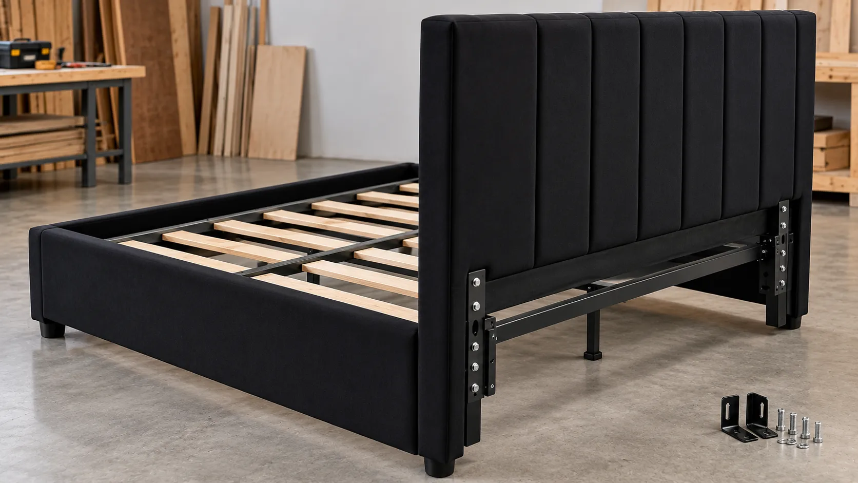
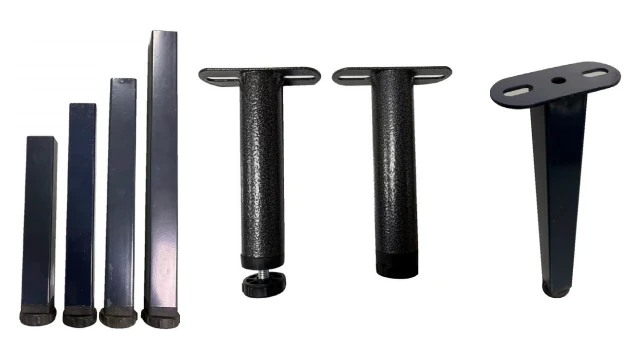
A visible outer bed leg, a center support leg and an adjustable foot are different components. Outer legs may connect to the bed surround or main frame. Center legs support a designated rail or crossmember beneath the mattress base. A leveling foot or glide may be only the lower adjustable part of an existing leg.
Before ordering, establish whether the missing or damaged item is the complete leg, the bottom foot, the threaded insert, or a bracket that connects the leg to the frame. Replacing the foot does not repair a damaged insert; replacing the tube does not correct a failed mounting point.
| Component | Where to look | What must be identified |
|---|---|---|
| Outer bed leg | Connection to the side rail, corner or surrounding bed structure | Fixing arrangement, installed height and whether it supports the frame, the surround or both |
| Center support leg | Designated position beneath a center rail or crossmember | Support location, attachment detail and specified floor-contact condition |
| Adjustable foot or glide | Bottom of a leg or its threaded insert | Stem specification, usable adjustment, retaining or locking parts and contact pad |
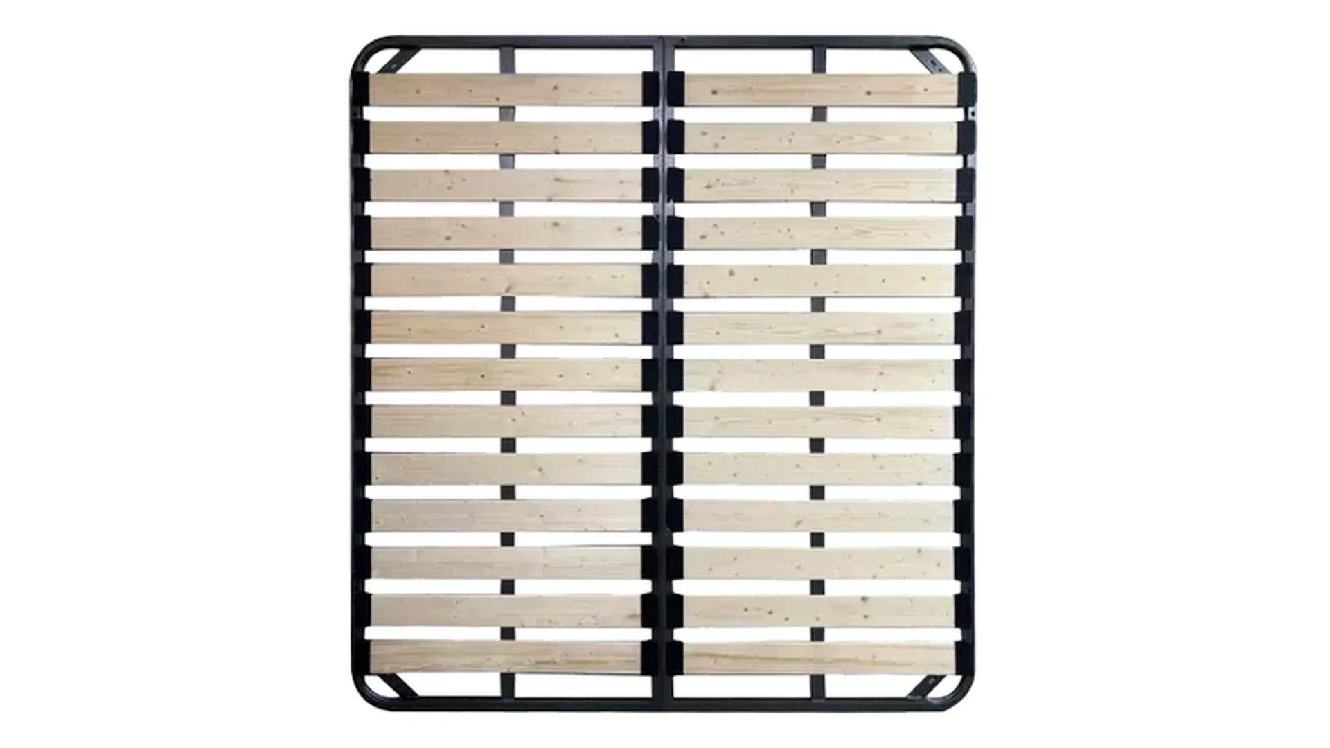
For custom furniture, identify the component within the complete support structure. Shilong’s folding double-row bed frame lists feet and bracket matching among its configuration options. That is a starting point for model-specific coordination, not evidence that one foot will fit every folding or upholstered bed.
Measure the Installed Height, Not Just the Loose Leg
Find the actual mounting reference
The relevant height is the distance the installed support must bridge. On a leg that seats directly against the underside of a rail, the reference may be that bearing surface and the finished floor. A side-mounted bracket can position the leg above or below the rail’s underside, so the same measurement cannot automatically be used.
Record the two physical reference points on a drawing or photograph. “Bed height” is too ambiguous: it might mean the mattress-support surface, the top of a side rail, or the finished mattress height. None of those necessarily equals the required leg height.
Take measurements with the frame assembled in the condition specified by its instructions, including the required outer supports. Do not use a bent or unsupported rail as the height reference. The condition of the floor also belongs in the record; measurements taken on one surface may not describe the installation on another.
Separate body length, inserted length and adjustment
A loose component can include a threaded stem, an insertion section, a mounting plate and a foot pad. Some of that length may disappear inside its mating part after assembly. Other portions may add to the installed height. The mounting drawing must show which dimensions are included.
Ask for the minimum and maximum permitted installed height, together with the corresponding engagement and locking requirements. A stem’s total length is not an adjustment allowance. Extending it until only a few threads remain engaged is not a valid way to create a taller support.
For example, a replacement with a similar overall length but a different bracket offset can leave the center rail either unsupported or pushed upward. This is a geometric mismatch even before load capacity is considered. Comparing the mounting reference and installed range exposes the problem earlier than comparing catalogue photographs.
Match the Mounting Interface Before Comparing Prices
A correct height does not compensate for the wrong connection. Compare the receiving part on the frame with the replacement leg as a matched pair. Do not force a fastener that begins to bind, enlarge holes or introduce an improvised adapter to make an uncertain match work.
| Interface | Information to record | Common comparison error |
|---|---|---|
| Threaded stem and socket | Thread designation, diameter and pitch; usable engagement; locking arrangement | Matching approximate diameter while overlooking pitch or the receiving insert |
| Mounting plate | Plate outline, hole center positions, mating surface, orientation and specified hardware | Matching plate size without matching the hole pattern |
| Bracket or clamp | Rail section, contact faces, bracket position and prescribed clamp or fastener | Assuming the bracket fits any rail of a similar apparent width |
| Insert or proprietary connection | Part number, receiving component and retention or locking method | Substituting a visually similar part without checking the complete connection |
When recording holes, measure between their centers and state their positions relative to an identified edge or reference. A photograph taken at an angle can help locate the part but is not a reliable dimensional drawing. Include a view of the receiving connection as well as the detached component.
Fastener length also needs context. A screw that enters a blind socket must fit the available depth; a screw used with a nut has a different engagement arrangement. Use the hardware specified for the assembly rather than selecting a longer screw because it appears more secure. The correct torque, where specified, is model-specific.
For a new bed design, resolve the interface before approving the support leg. Keep the plate, insert, bracket and fasteners together in the component specification. Otherwise, two suppliers can both offer a “matching leg” while working from different assumptions about the receiving frame.
Check the Usable Adjustment Range and Floor Contact
An adjustable support is useful only when the required height falls within its approved operating range. The adjustment must retain the specified engagement and locking arrangement. Some systems use a separate locknut; others use a different retention mechanism. Their settings are not interchangeable.
Leggett & Platt’s published 0061/10061 assembly instructions, for example, identify a leg, insert, glide and locking nut separately and set an engagement requirement for that system. The lesson is to obtain the equivalent instructions for the actual part—not to copy another manufacturer’s dimension onto a Shilong frame.
Too short and too long are different problems
On a design that requires the center support to touch the floor, a gap can prevent that support from carrying its intended share of the load. Conversely, extending the center leg too far can lift the frame and alter contact at other support points. Dreams’ bed troubleshooting guidance identifies both conditions as possible causes of instability.
Check the complete assembly after adjustment: the center support, outer supports, rail alignment and any specified clearances. Follow the model’s instructions for the relevant unloaded or loaded condition. Do not turn the center leg into a jack to raise the bed or attempt to cure a bent rail by extending it.
In a custom project, frame height and support-leg height should be coordinated rather than ordered independently. When reviewing Shilong’s bed frame range, select the support drawing for the actual ordered configuration. A chosen frame height does not, by itself, define a universal replacement leg.
Keep the intended contact arrangement
Confirm whether the approved assembly includes a foot pad, cap, glide or other floor-contact component. Adding an unapproved spacer changes the installed height and contact arrangement. Removing a pad to gain clearance can also change how the component sits. Resolve these changes with the supplier rather than treating them as cosmetic adjustments.
Do not reach beneath a bed supported only by a person, loose blocks or an unsecured lifting arrangement. Any access, unloading or disassembly should follow the product’s instructions and a safe working method.
A Leg That Fits Is Not Automatically a Structural Upgrade
Dimensional fit and structural suitability are separate decisions. The leg connects to a rail, bracket or insert that must also be suitable for the intended loading. A stronger-looking component does not establish that its receiving connection, or the rest of the bed, can carry more weight.
Do not add a standalone leg’s advertised capacity to the frame’s stated capacity. Nor should extra feet be installed wherever there is convenient clearance. Their positions must belong to an approved support arrangement, particularly where a folding frame or moving mechanism needs space to operate.
Check the receiving component for damage before treating a replacement as a solution. A distorted plate, damaged thread, cracked weld or bent rail calls for assessment of the affected structure. Stop using a bed that shows unsafe structural damage; tightening or replacing one leg is not a substitute for that assessment.
For OEM development, approval should cover the leg within the specified bed assembly. A useful record connects the exact component and mounting detail to the frame revision and relevant evaluation. Without that connection, a test result for a different part or configuration cannot resolve the compatibility question.
Create a Support-Leg Matching Record Before Ordering
A focused matching record reduces ambiguity without turning a small replacement into a generic factory audit. Keep photographs and measurements together so the supplier can see what each dimension describes.
| Record | Include |
|---|---|
| Bed and component identity | Bed model or drawing revision, original part reference, quantity and support position |
| Height requirement | Named measurement references, required installed height and the floor/assembly condition used |
| Mounting detail | Receiving connection, thread or hole information, bracket orientation and existing hardware |
| Adjustment | Required range and the supplier’s engagement, retention and locking instructions |
| Condition | Clear photographs of the original leg and receiving part, with any damage identified |
For replacements, the first choice is an identified compatible part or a supplier-approved alternative. For a new frame, review the drawing and assembled sample before freezing the component specification. Photographs help that discussion, but they cannot establish concealed dimensions or prove structural safety.
The right bed frame support leg is the one that fits the specified mount, reaches the required installed height within its permitted range, and remains suitable for the complete support arrangement. To discuss bed-frame and support-leg matching with Shilong, provide those measurements, the frame drawing or model, connection photographs and the intended quantity.